1. Introduction
The global energy landscape is undergoing a significant transformation, driven by the need for sustainable and environmentally friendly alternatives. In this context, renewable energy sources have gained prominence as a viable solution to address the challenges posed by conventional fossil fuels. Bangladesh, a densely populated country in South Asia, faces its own unique energy scenario. This chapter explores the current state of power generation in Bangladesh, with a specific focus on renewable energy. We delve into the contribution of renewable sources, their future prospects, challenges, and limitations. Total Installed Capacity Bangladesh’s total installed electricity generation capacity has been increasing steadily over the years and was estimated to be around 22,000 megawatts (MW) as of 2023. This capacity includes both thermal (such as natural gas and coal) and renewable energy sources
| [1] | M. N. Uddin, M. A. Rahman, M. Mofijur, J. Taweekun, K. Techato, and M. G. Rasul, “Renewable energy in Bangladesh: Status and prospects,” Energy Procedia, vol. 160, pp. 655-661, Feb. 2019, https://doi.org/10.1016/j.egypro.2019.02.218 |
[1]
. Bangladesh's energy sector is heavily reliant on natural gas, historically contributing 60-70% of the total energy mix due to its extensive use in electricity generation, industry, and households. Coal-fired power plants, aimed at diversifying energy sources, now account for 10-15% of energy consumption. Fuel oil, primarily for backup power and industrial needs, contributes 5-10%, while hydropower remains modest at less than 5% due to limited resources. Solar energy, driven by governmental incentives and expanding rural use, has grown to 2-3%. Despite significant growth, the sector faces challenges like capacity shortages, load shedding, and fossil fuel dependency, necessitating sustainable energy solutions to meet rising demand
. Microgrids are emerging as a pivotal innovation in the energy landscape. Functioning as localized energy networks, they ensure power supply to nearby users during grid failures, while also offering cost management, energy resilience, and carbon emissions reduction benefits. These systems can support the main grid during times of strain or imbalance. A microgrid is essentially an independent energy system serving a specific area like a university campus, factory, hospital complex, or neighborhood. It operates autonomously, generating power on-site and can serve as a backup during emergencies. Utilizing various energy sources such as renewables, energy storage, combined heat and power, or generators, microgrids are designed to operate reliably in all conditions. Their distinguishing feature lies in their ability to operate both connected to and disconnected from the main grid, depending on the situation. During disasters like storms or blackouts, microgrids can isolate themselves from the main grid to ensure continued power supply to the buildings they serve
| [3] | F. Alasali et al., “Powering up microgrids: A comprehensive review of innovative and intelligent protection approaches for enhanced reliability,” Energy Rep., vol. 10, pp. 1899-1924, Nov. 2023, https://doi.org/10.1016/j.egyr.2023.08.068 |
[3]
. Microgrids also assist local utilities in managing the increasing number of distributed energy resources, including solar panels, smart buildings, electric vehicles, and batteries. With advanced controllers and software, they can efficiently manage energy operations, optimizing generation resources based on various factors like weather conditions, pricing fluctuations, or resource availability. Each microgrid is tailored to the needs of its users, ranging from individual buildings to larger entities like communities or business parks
| [4] | S. Molla, M. Shawon, M. Nawaj, and A. Emon, “Analysis of Aging Effect and Cell Balancing Problem of Lithium-Ion Battery,” J. Electr. Electron. Eng., vol. 13, no. 2, pp. 92-107, Mar. 2025, https://doi.org/10.11648/j.jeee.20251302.11 |
[4]
. They utilize diverse energy sources, including solar, wind, fuel cells, and hydroelectricity, depending on the specific requirements. During power outages, microgrids offer more reliable and finely tuned backup compared to traditional generators. Regular generators lack the sophisticated energy management capabilities necessary during emergencies and are prone to failures. In contrast, microgrids are regularly maintained and draw from multiple energy sources, ensuring continuity of power supply even if one source fails. This redundancy makes them more resilient to fuel shortages or other disruptions, providing a more dependable solution during crises. Renewable energy-based microgrids are increasingly favored in power systems due to their ability to improve reliability and reduce power losses
| [5] | H. Jiayi, J. Chuanwen, and X. Rong, “A review on distributed energy resources and MicroGrid,” Renew. Sustain. Energy Rev., vol. 12, no. 9, pp. 2472-2483, Dec. 2008, https://doi.org/10.1016/j.rser.2007.06.004 |
[5]
. To ensure their effectiveness, robust control strategies are crucial, particularly considering the complex nonlinear dynamics inherent in these systems. This paper offers a thorough examination of robust control techniques for microgrids, encompassing AC, DC, and hybrid configurations, as well as various interconnections with conventional power systems. Drawing from recent research, it discusses the key control objectives and proposed methods, comparing their applicability across different microgrid types. Additionally, the article highlights existing research gaps, such as scalability issues, robustness evaluation, and assessment methodologies, and suggests avenues for future research to enhance the performance of robust controllers in AC, DC, and hybrid microgrid contexts
| [5] | H. Jiayi, J. Chuanwen, and X. Rong, “A review on distributed energy resources and MicroGrid,” Renew. Sustain. Energy Rev., vol. 12, no. 9, pp. 2472-2483, Dec. 2008, https://doi.org/10.1016/j.rser.2007.06.004 |
[5]
.
3. Methodology
3.1. Introduction
In pragmatic frameworks, uncertainties and parameter annoyance generally exist are normal and can fundamentally impact control framework execution and security. Planning robust controller within the sight of parametric uncertainties is fundamental, yet getting a careful determined model is frequently difficult because of different variables like environmental noise (harmonics) and data error and aging
| [12] | B. Dhanasekaran, J. Kaliannan, A. Baskaran, N. Dey, and J. M. R. S. Tavares, “Load Frequency Control Assessment of a PSO-PID Controller for a Standalone Multi-Source Power System,” Technologies, vol. 11, no. 1, p. 22, Jan. 2023, https://doi.org/10.3390/technologies11010022 |
[12]
. Throughout recent many years, significant exertion has been committed to tending to hearty security and adjustment issues in linear system with parameter uncertainty. Different design techniques have been created and applied to solve these practical issues. Researchers across multiple domains of control systems are increasingly emphasizing robust analysis of uncertain linear systems. Through feedback control techniques, solutions to the robust stabilization problem for both continuous- and discrete-time plant models have been achieved. However, addressing challenges such as computational complexity, methodologies such as static result criticism regulators and approaches dealing with Bilinear Matrix Inequality (BMI) constraints have been explored. Some studies have established stability conditions within the Linear Matrix Inequality (LMI) framework, often requiring a predetermined selection of the Lyapunov matrix
| [12] | B. Dhanasekaran, J. Kaliannan, A. Baskaran, N. Dey, and J. M. R. S. Tavares, “Load Frequency Control Assessment of a PSO-PID Controller for a Standalone Multi-Source Power System,” Technologies, vol. 11, no. 1, p. 22, Jan. 2023, https://doi.org/10.3390/technologies11010022 |
[12]
.
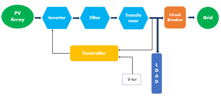
Figure 1. Block diagram for micro-grid control.
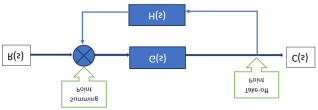
Figure 2. The way of controlling microgrids.
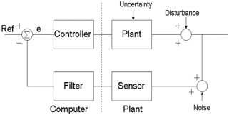
Figure 3. Microgrid control overview.
A few techniques lay out strength conditions inside the Direct Lattice Imbalance (LMI) structure, while others center on blended H2/H∞ union issues or quadratic hearty adjustment of nonlinear frameworks. Onlooker based regulator plan techniques have likewise been created to deal with standard limited vulnerabilities in straight frameworks.
In this paper, another static state criticism regulator configuration approach is proposed for straight questionable frameworks utilizing the Lyapunov soundness approach. This technique presents another arrangement of adequate circumstances integrating data from the base eigenvalue of annoyance frameworks. This original methodology is exhibited through mathematical models, showing its adequacy and predominance over existing strategies. Additionally, by imposing additional constraints in the design framework, the proposed method reduces control effort. The use of LMI formulation offers computational advantages, making the design process more efficient. The proposed technique is validated through numerical examples, highlighting its superiority over existing methods in terms of performance and efficiency
| [13] | S. K. Sarkar, F. R. Badal, and S. K. Das, “A comparative study of high performance robust PID controller for grid voltage control of islanded microgrid,” Int. J. Dyn. Control, vol. 6, no. 3, pp. 1207-1217, Sep. 2018, https://doi.org/10.1007/s40435-017-0364-0 |
[13]
.
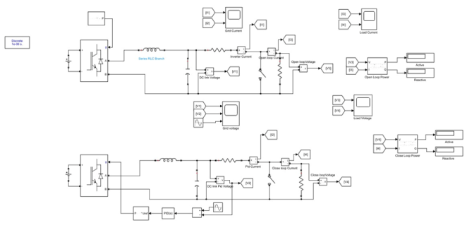
3.2. Microgrid Configuration
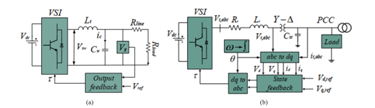
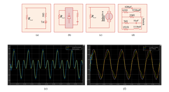
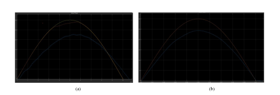
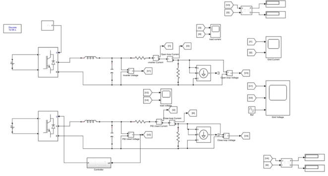
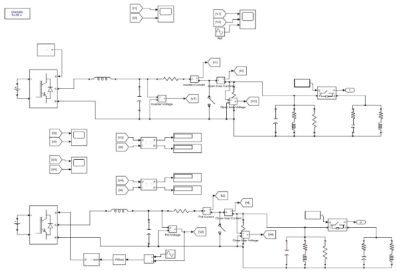
Figure 4 (a) depicts the design of a single-phase energy source Microgrid (MG) aimed at dissecting and evaluating its performance. The system comprises a DC voltage source (Vdc), an LC filter, a voltage source inverter (VSI), and line and load impedance. VSIs are positioned between the grid network and the DC voltage source to facilitate power transfer from the DC side to the AC side. Under steady-state conditions, the average AC power (Pac) equals the DC power (Pdc). The VSI is composed of Insulated Gate Bipolar Transistors (IGBTs), with the switching action of each IGBT defined by V
SW= τV
dc, where δ represents the duty ratio within the range of [-1, 1]. To mitigate switching ripple in power solid-state devices, LC filters are employed. Additionally, a shunt capacitor (C
ST) is utilized to mitigate the impact of high-frequency harmonics.
Figure 4 (b) illustrates a three-phase Microgrid (MG) with analogous components to those in
Figure 4 (a), with the addition of transformers (Tx). These transformers are utilized to transfer power from the distribution generation station to the low-high voltage line, aiming to diminish line losses and transmission expenses.
3.3. Voltage Control
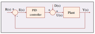
The block diagram illustrating the voltage control of an MG system, as depicted in
Figure 3, involves tracking the desired grid voltage (Vg) for each Voltage Source Inverter (VSI) through a voltage control loop. The switching frequency of the VSI hinges on a duty ratio, crucial for achieving precise voltage tracking. This duty ratio, determined by the controller within the range of [-1, 1], employs pulse width modulation (PWM) principles. Within the voltage control loop, the grid voltage is generated by the VSI and compared with the desired reference MG voltage. Furthermore, to ensure accurate voltage tracking, the control loop necessitates a high bandwidth
| [15] | S. H. Sikder, Md. M. Rahman, S. K. Sarkar, and S. K. Das, “Fractional Order Robust PID Controller Design for Voltage Control of Islanded Microgrid,” in 2018 4th International Conference on Electrical Engineering and Information & Communication Technology (iCEEiCT), Dhaka, Bangladesh: IEEE, Sep. 2018, pp. 234-239. https://doi.org/10.1109/CEEICT.2018.8628040 |
[15]
.
3.4. Modeling Single Phase
From the
Figure 4 (a) the inductor current
is given by the following equation:
Where, and the capacitor and grid current respectfully. The controller design is based on:
The switching voltage over pulse width modulation (PWM) is given by:
For grid voltage
From (
2) and (
4), the derived state-space model is:
In this microgrid system, the state vector xx and the input vector uu represent the system's current state and input, respectively. The disturbances, denoted by dd, are closely associated with the state and input vectors. These disturbances lead to grid current fluctuations due to the inherent uncertainty in the microgrid structure. This uncertainty arises from challenges in controlling, tuning, and the dynamic nature of the microgrid, especially when loads or generators are switched on or off.
The state space is as follows:
(8)
The output of the system is:
3.5. Modeling of Three Phase Microgrid
The modeling of the three-phase mg is illustrated in
Figure 4 (b). The governing equation of the open loop system can be defined in
frame as follows
(10)
The transformation of the dynamic system in (
9)-(
10) from
frame to
reference is derived as
(12)
Finally, the above equation (
11) - (
12) are transformed to
rotating frame and the resultant equation are presented as
(14)
(15)
Were,
. The state space representation of the open loop tree phase MG in (
13)-(
14) is written as,
,and
The state matrices are defined as
’’(16)
,,(17)
Here is the state vector; is input vector,
is the exogenous input vector and output vector is defined as?
| [16] | S.-H. Hwang and H.-C. Chang, “A theoretical examination of closed-loop properties and tuning methods of single-loop PI controllers,” Chem. Eng. Sci., vol. 42, no. 10, pp. 2395-2415, 1987, https://doi.org/10.1016/0009-2509(87)80113-6 |
[16].
3.6. Robust PID Controller Design
This section introduces the foundation of employing a Linear Quadratic Regulator (LQR) as the basis for designing a robust PID controller. LQR control theory is known for its notable robustness, as evidenced in various control problems. The controller design in this context relies on principles derived from LQR control theory. Specifically, we consider a Linear Time-Invariant (LTI) system,
Where, is the control signal, which minimize the quadratic cost function,
For any initial state
, where
and
, i.e.,
and
are symmetric positive semi-definite matrix and symmetric positive definite matrix, respect fully. Letting that
and
are controllable and observable respectfully. Then the optimal control minimizing
is given by the linear sate feedback law
| [17] | M. C. Joshi and S. Samanta, “Modeling and control of bidirectional DC-DC converter fed PMDC motor for electric vehicles,” in 2013 Annual IEEE India Conference (INDICON), Mumbai, India: IEEE, Dec. 2013, pp. 1-6. https://doi.org/10.1109/INDCON.2013.6726091 |
[17]
,
where P is the positive definite solution of the Algebraic Riccati Equation (ARE),
And the minimum quadratic cost is given by,
Solving of ARE (
17) is most important for the solution of LQR problem. By applying linear matrix inequality (LMI) technique, the LQR problem can be rewritten as an optimization problem over
and
| [18] | P. Sharma and A. Dhawan, “Robust Non-Fragile Control of 2-D Discrete Uncertain Systems: An LMI Approach,” J. Signal Inf. Process., vol. 03, no. 03, pp. 377-381, 2012, https://doi.org/10.4236/jsip.2012.33049 |
[18]
(22)
Subject to
(23)
Where
and
in many cases equation (
19) is rewritten as,
Where the specified upper bound. The above inequality is can be written as LMI,
(25)
So, the optimization problem in (
19), (
20) is converted to find a solution (
) which is satisfies a set of LMIs in (
20) and (
22). For this the state feedback gain is given by,
But in repetition the system matrix is not precisely known. Assume that is uncertain but lies in a polytypic set,
(27)
Where refers to if
(28)
Where refers to the number of multiple models and refers the weighting functions constrained between 0 and 1 and satisfy,
Normally, LMIs in (
19) and (
20) are used to find solutions over all uncertain system
. But it is a challenging task. However, due to the characteristics of polytopic systems, finding a solution only at the polytopic vertices is enough instead of all points within the polytopic.
3.7. Design of PID Controller
In this section, we outline the methodology for designing a PID controller tailored for a microgrid system employing an LMI-based approach. The microgrid system, as described in equations (
5) and (
6), is characterized as a second-order system. Consequently, the controller design is tailored specifically for second-order systems. The closed-loop system's block diagram is depicted in
Figure 2. We proceed under the assumption of an uncertain second-order system
| [19] | B. Lin, X. Su, and X. Li, “Fuzzy Sliding Mode Control for Active Suspension System with Proportional Differential Sliding Mode Observer,” Asian J. Control, vol. 21, no. 1, pp. 264-276, Jan. 2019, https://doi.org/10.1002/asjc.1882 |
[19]
,
Where the parameters, and vary in an interval,
(30)
Where, and are lower and upper bound for denominator and numerator of the system, respectfully. The structure of a PID controller is as follows,
Or,
Where and are the proportional gain, integral gain and derivative gain, respectfully
Adjusting the proportional gain (KP) leads to a reduction in rise time, while the integral gain (Ki) helps minimize steady-state error, albeit at the expense of potentially increasing overshoot. On the other hand, the derivative gain (Kd) aids in decreasing overshoot and settling time. The primary objective of PID controller design is to determine the optimal PID settings that fulfill various design requirements. The feedback system's state-space representation can be expressed as,
Where is the output of the system, is the state i.e., and the reference input?
,,,(34)
In this context, the PID controller design transitions into a static state feedback controller, where the feedback gain KK encapsulates the parameters of the PID controller. Equations (
26) and (
31) introduce three uncertain parameters. Furthermore, the polytopic uncertain set specified in (
24) simplifies to.
(35)
Where the vertex matrix are determined based on the system identification results.
The outlines the design and implementation of an advanced microgrid controller tailored for managing the complexities of diverse load conditions and ensuring robust stability. It introduces a Linear Matrix Inequality (LMI)-based framework combined with PID controllers to address challenges such as parametric uncertainties, environmental noise, and system dynamics. The controller's development involves the use of a Lyapunov stability approach and the transformation of control problems into optimization tasks solved via LMI techniques, ensuring efficient computation and robustness
| [3] | F. Alasali et al., “Powering up microgrids: A comprehensive review of innovative and intelligent protection approaches for enhanced reliability,” Energy Rep., vol. 10, pp. 1899-1924, Nov. 2023, https://doi.org/10.1016/j.egyr.2023.08.068 |
[3]
. A systematic modeling of microgrid configurations—both single-phase and three-phase systems—is provided. These models incorporate key components like voltage source inverters, LC filters, and transformers, with detailed equations describing power transfer and system dynamics. A state-space representation is utilized to capture the system's behavior, and disturbances are accounted for to enhance controller adaptability
| [13] | S. K. Sarkar, F. R. Badal, and S. K. Das, “A comparative study of high performance robust PID controller for grid voltage control of islanded microgrid,” Int. J. Dyn. Control, vol. 6, no. 3, pp. 1207-1217, Sep. 2018, https://doi.org/10.1007/s40435-017-0364-0 |
[13]
. To achieve optimal performance, the methodology integrates a Linear Quadratic Regulator (LQR) as the foundation for PID controller design. The LQR principles are adapted to minimize quadratic cost functions and derive state feedback laws, ensuring stability even under uncertainties. The PID controller gains (proportional, integral, and derivative) are fine-tuned to achieve desired system dynamics, such as reduced rise time, steady-state error, and overshoot. This robust approach is validated through numerical examples, demonstrating its efficacy in handling harmonic, non-linear, and dynamic load conditions, as well as its ability to maintain voltage and current stability across a range of operating scenarios
| [13] | S. K. Sarkar, F. R. Badal, and S. K. Das, “A comparative study of high performance robust PID controller for grid voltage control of islanded microgrid,” Int. J. Dyn. Control, vol. 6, no. 3, pp. 1207-1217, Sep. 2018, https://doi.org/10.1007/s40435-017-0364-0 |
[13]
. The methodology establishes a scalable and adaptable framework for modern microgrid systems, addressing the demands of renewable energy integration and real-world uncertainties.
4. Result and Discussion
4.1. Introduction
This section provides a comprehensive evaluation of the improved microgrid controller, showcasing its performance under diverse load conditions, including harmonic, non-linear, dynamic, asynchronous machine, and unknown loads. It emphasizes the controller's ability to manage distortions effectively, ensuring voltage and current stability, even under challenging scenarios. By employing a Linear Matrix Inequality (LMI)-based PID controller, the system demonstrates a significant reduction in Total Harmonic Distortion (THD) and robust operation against variations in load characteristics. The controller's adaptability allows it to maintain system reliability and stability, handling the complexities of real-world conditions such as fluctuating inductance, capacitance, and resistance. This highlights the controller's potential for ensuring consistent microgrid performance, making it a valuable solution for modern energy systems that demand resilience and precision.
4.2. Harmonic Loads
In an electric power system, non-linear loads such as computers, printers, fluorescent lamps, televisions, rectifiers, and battery chargers introduce harmonics, as depicted in
Figure 7. These harmonics cause distortions in voltage and current, compromising the quality of the electric power supply. The presence of harmonic voltages results in increased heating in both the load and conductors, consequently shortening the lifespan of electric loads. Moreover, when connected to the electric power system, non-linear loads draw power, leading to non-sinusoidal current waveforms due to load dependencies and voltage distortion caused by source impedance. Harmonics are distortions in electrical systems caused by non-linear loads, which generate currents and voltages at frequencies that are multiples of the fundamental frequency. These distortions can degrade the performance and efficiency of power systems. Among these, 3rd order harmonics are particularly problematic as they significantly increase system current levels, potentially leading to overheating, reduced equipment lifespan, and operational inefficiencies. To address these issues, a voltage controller is employed to manage inverters, which play a crucial role in mitigating harmonic effects.
Figure 6. Harmonic load Circuit Diagram.
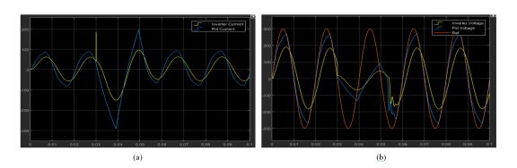
For instance, when a 30 Ω resistor is connected in series, the resulting current waveform exhibits a frequency of 150 Hz (3rd harmonic of a 50 Hz system) with an amplitude of 7 A. This demonstrates the generation of 3rd order harmonics under such load conditions. The effectiveness of the proposed voltage controller in handling harmonic loads is illustrated through results, as shown in
Figure 7 (e) and (f). These figures demonstrate that the controller performs reliably by maintaining system stability and robustness, even in the presence of diverse harmonic disturbances. This indicates the controller’s capability to ensure consistent system performance and safeguard against the adverse effects of harmonic loads.
4.3. Non-linear Loads
This explanation describes a contour plot showcasing how a microgrid system performs when subjected to non-linear loads. Non-linear loads are electrical devices that draw current in a non-linear manner, meaning the current waveform does not align with the voltage waveform. Common examples include appliances like refrigerators, air conditioners, televisions, and computers, which are increasingly used in households and industries globally. In this simulation, a specific type of non-linear load is used to represent these devices—a two-phase four-pulse diode bridge rectifier. This component serves as a simplified model to replicate the behavior of non-linear loads. It is connected to the point of common coupling (PCC), which is the location in the microgrid where different electrical systems interconnect. By doing so, the simulation evaluates how the microgrid responds to the challenges posed by these loads, such as power quality issues, harmonics, and efficiency, which are critical for real-world applications. The contour plot effectively visualizes these performance metrics and their variations across different conditions.
Figure 8. Non-linear load Circuit Diagram.
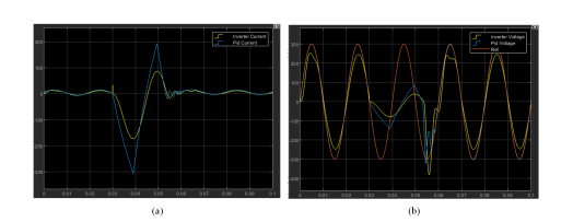
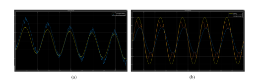
The passage describes a system in which an output terminal is connected to a resistive-capacitive (RC) load. The RC load is specified with a resistance (R) of 80 ohms and a capacitance (C) of 5 microfarads (5 μF). This setup is analyzed to measure total harmonic distortion (THD), a key metric for evaluating distortions caused by non-linear loads, following the standardized guidelines of the IEEE. The figures referenced (
Figure 9 (a) and (b)) illustrate how a Linear Matrix Inequality (LMI)-based PID controller improves the management of such non-linear loads. These controllers are specifically designed to regulate the system by ensuring the load behaves in a predictable and controlled manner, even under non-linear conditions. The findings from these figures highlight two significant outcomes of using this controller:
Stability: The system maintains steady performance without oscillations or deviations under varied operating conditions.
Robustness: It demonstrates resilience against disturbances, ensuring reliable operation despite potential variations in load characteristics.
The LMI-based PID controller effectively handles the challenges posed by non-linear loads, maintaining a high-performance standard as verified by the THD measurements.
Figure 9. Output diagram of Non-linear load (a) Current (b) Voltage.
4.4. Dynamic Loads
This test aims to assess how effectively the controller can maintain stable operation of the microgrid under varying dynamic loads. Dynamic loads, which involve changes in active and reactive power demands, challenge the system's ability to sustain voltage stability. In this scenario, the test begins with the active power set to 50 MW and the reactive power to 25 MW. These variations impose considerable stress on the power system, influencing its overall stability.
Figure 10. Dynamic load Circuit Diagram.
Fault currents, which arise during open and short circuit conditions, are critical in such evaluations. An open circuit fault occurs when a break in the circuit disrupts the flow of current, effectively cutting off power.
Figure 11. Output diagram of dynamic load (a) Current (b) Voltage.
In contrast, a short circuit fault creates a low-resistance path, leading to a sudden surge of current. This surge can cause significant stress on connected loads, potentially damaging them and compromising their functionality. The controller's ability to respond to these dynamic and fault conditions is critical for ensuring the microgrid's reliability. The outcomes of this test, showcasing how the controller handles such challenges, are visually represented in
Figure 11 (a) and (b).
4.5. Asynchronous Machine Loads
In this simulation, the proposed controller's performance is evaluated when managing the dynamics introduced by asynchronous machine loads. For this study, an induction motor is selected as the representative asynchronous machine. The modeling of this motor is carried out using a dq stator reference frame, which allows for detailed analysis of its behavior in response to system changes. The motor configurations include capacitor-start and capacitor-start-run, which are common in practical applications.
Figure 12. Motor's operation.
These configurations reflect how the motor starts and operates, accounting for variations in its power demand and operational stability. The induction motor is connected in parallel with a microgrid, forming part of the power system. This setup is crucial as the motor's operation introduces variations in active and reactive power, directly influencing the overall dynamics of the microgrid. Such fluctuations pose challenges to the stability and efficiency of the power system, making it a valuable test case for assessing the effectiveness of the controller.
Figures 13 (a) and (b) illustrate the results of the simulation, providing insights into how well the controller manages these challenges. Meanwhile,
Figure 13 offers a schematic representation of the system under analysis, further clarifying the setup used in the evaluation.
Figure 13. Output diagram of Asynchronous machine load (a) Current (b) Voltage.
4.6. Unknown Loads
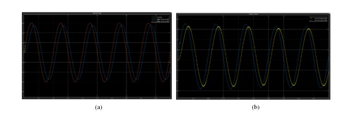
The discussion emphasizes evaluating how dependable and resilient the proposed controller is when managing unpredictable or unknown loads in the microgrid system. In this context of
figure 14 illustrates the model of an unknown load, which is connected in parallel with the microgrid. This setup allows for assessing the microgrid's response to load changes. When the switch connecting the load is closed, a noticeable change occurs in the steady-state conditions of the system at approximately 0.3 seconds. This change is characterized by variations in the system's inductance, capacitance, and resistance. Despite the introduction of unknown loads, the controller demonstrates remarkable stability, ensuring that the peak amplitude of the microgrid voltage remains constant under all conditions. To further validate performance,
Figure 14 provides visual insights. Sub
figure 15 (a) showcases how the voltage of the microgrid tracks effectively, maintaining consistency even with unknown loads. Sub
figure 15 (b) highlights the fault current tracking, demonstrating the controller's capability to handle disruptions or faults robustly.
Figure 14. Unknown load Circuit Diagram.
Figure 15. Output diagram of Asynchronous machine load (a) Current (b) Voltage.
4.7. Output Comparison with Normal Microgrid Controller
Figure 16. Improved Microgrid Controller Output (a) Grid voltage (b) Current.
Microgrid controllers are essential for ensuring stable and efficient operation of microgrids. The performance of these controllers varies depending on the type of load connected to the system. Here's a summary of how an improved microgrid controller compares to a normal microgrid controller across different load types,
Harmonic Load:
Normal Controller: Struggles with harmonic distortion, leading to power quality issues such as voltage and current harmonics.
Improved Controller: Utilizes advanced filtering and harmonic compensation techniques, reducing harmonic distortion and improving power quality.
Non-linear Load:
Normal Controller: May not effectively manage the distorted waveforms caused by non-linear loads (variable-speed drives), leading to power factor issues and voltage instability.
Improved Controller: Incorporates sophisticated algorithms to handle non-linear loads, compensating for Total Harmonic Distortion (THD) and ensuring stable voltage and current waveforms.
Asynchronous Load:
Normal Controller: Faces difficulty synchronizing with asynchronous loads (e.g., wind turbines), which can lead to frequency and voltage instability.
Improved Controller: Uses advanced techniques like frequency droop control or virtual synchronous machines (VSM) to synchronize with asynchronous loads, maintaining system stability.
Unknown Load:
Normal Controller: Has limited ability to adapt to sudden or unpredictable changes in load, causing potential disruptions in the system.
Improved Controller: Features adaptive control and load forecasting capabilities, enabling it to adjust to unknown or fluctuating loads and maintain stable operation.
Figure 17. Normal Microgrid Controller Output (b) Grid voltage (a) Current.